VRF(Virtual Routing and Forwarding)とはルーティングテーブルの仮想化技術です。1台のルータ・L3スイッチで複数のルーティングテーブルを保持するテクノロジーでレイヤー2レベルの仮想化技術がVLAN、レイヤー3レベルの仮想化がVRFと覚えて良いとおもいます。
VRFはMPLS-VPNで使われている技術でありますが、私自身、MPLS-VPNの構築経験はありません。ただ、MPLS-VPNを構築する機会がないといえどVRFを単体で使用することは実務でもよくあります。それだけ使える技術ということだと思います。
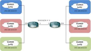
上の図を元に紹介できればと思います。
各ルータ配下に接続するセグメントは全て同一ですがVRFを使うことにより各セグメントは完全に独立した形で動いておりルータ上でも交わることはありません。
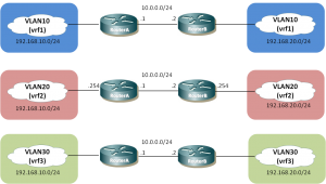
左側と右側で同一の色で塗りつぶしたところが同じVRFに所属する形となりルータを介して相互に通信可能となります。上記は物理的な構成図であり、VRFを踏まえた論理的な構成図で表す と下記のようになります。
それでは上記Routerの実際の設定をみていきます。RouterAの設定内容は以下のようになります。
ip vrf vrf1 ! ip vrf vrf2 ! ip vrf vrf3 ! interface FastEthernet0/0 description : To LAN no ip address duplex auto speed auto ! interface FastEthernet0/0.10 encapsulation dot1Q 10 ip vrf forwarding vrf1 ip address 192.168.10.254 255.255.255.0 ! interface FastEthernet0/0.20 encapsulation dot1Q 20 ip vrf forwarding vrf2 ip address 192.168.10.254 255.255.255.0 ! interface FastEthernet0/0.30 encapsulation dot1Q 30 ip vrf forwarding vrf3 ip address 192.168.10.254 255.255.255.0 ! interface FastEthernet0/1 description : To WAN no ip address duplex auto speed auto ! interface FastEthernet0/1.10 encapsulation dot1Q 10 ip vrf forwarding vrf1 ip address 10.0.0.1 255.255.255.0 ! interface FastEthernet0/1.20 encapsulation dot1Q 20 ip vrf forwarding vrf2 ip address 10.0.0.1 255.255.255.0 ! interface FastEthernet0/1.30 encapsulation dot1Q 30 ip vrf forwarding vrf3 ip address 10.0.0.1 255.255.255.0 ! router ospf 10 vrf vrf1 router-id 1.1.1.1 log-adjacency-changes network 10.0.0.0 0.0.0.255 area 0 network 192.168.10.0 0.0.0.255 area 0 ! router ospf 20 vrf vrf2 router-id 2.2.2.2 log-adjacency-changes network 10.0.0.0 0.0.0.255 area 0 network 192.168.10.0 0.0.0.255 area 0 ! router ospf 30 vrf vrf3 router-id 3.3.3.3 log-adjacency-changes network 10.0.0.0 0.0.0.255 area 0 network 192.168.10.0 0.0.0.255 area 0 |
RouterBの設定内容は以下のようになります。
ip vrf vrf1 ! ip vrf vrf2 ! ip vrf vrf3 ! interface FastEthernet0/0 description : To LAN no ip address duplex auto speed auto ! interface FastEthernet0/0.10 encapsulation dot1Q 10 ip vrf forwarding vrf1 ip address 192.168.20.254 255.255.255.0 ! interface FastEthernet0/0.20 encapsulation dot1Q 20 ip vrf forwarding vrf2 ip address 192.168.20.254 255.255.255.0 ! interface FastEthernet0/0.30 encapsulation dot1Q 30 ip vrf forwarding vrf3 ip address 192.168.20.254 255.255.255.0 ! interface FastEthernet0/1 description : To WAN no ip address duplex auto speed auto ! interface FastEthernet0/1.10 encapsulation dot1Q 10 ip vrf forwarding vrf1 ip address 10.0.0.2 255.255.255.0 ! interface FastEthernet0/1.20 encapsulation dot1Q 20 ip vrf forwarding vrf2 ip address 10.0.0.2 255.255.255.0 ! interface FastEthernet0/1.30 encapsulation dot1Q 30 ip vrf forwarding vrf3 ip address 10.0.0.2 255.255.255.0 ! router ospf 10 vrf vrf1 router-id 4.4.4.4 log-adjacency-changes network 10.0.0.0 0.0.0.255 area 0 network 192.168.20.0 0.0.0.255 area 0 ! router ospf 20 vrf vrf2 router-id 5.5.5.5 log-adjacency-changes network 10.0.0.0 0.0.0.255 area 0 network 192.168.20.0 0.0.0.255 area 0 ! router ospf 30 vrf vrf3 router-id 6.6.6.6 log-adjacency-changes network 10.0.0.0 0.0.0.255 area 0 network 192.168.20.0 0.0.0.255 area 0 |
最初にVRFを定義しています。(vrf1-3)その後、インターフェイスにサブインターフェイスを作成し、dot1qを指定した 後にVRFを指定しています。OSPFやスタティックルートの設定の際にもVRFを指定する必要があります。(レイヤー3レベルですので)RouterBに関してもほぼ同様な設定となります。OSPFプロセスに関してもVRFごとに設定する必要があります。上の設定例だとrouter-idに実際に設定されていないものを設定していますが、重複がなければ問題ありません。
各VRFごとのインターフェイスのIPアドレスを同じものに設定しています。物理インターフェイスのIPアドレスがrouter-idとなりますが、router-idが重複してしまい動作結果としてOSPFネイバーがはれないということになってしまいますので、明示的なrouter-idを設定しています。 VRFを定義した場合、ルーティングテーブルを表示するにはVRF名を指定する必要があります。
RouterA# show ip route vrf vrf1

Routing Table: vrf1
Codes: C - connected, S - static, R - RIP, M - mobile, B - BGP
       D - EIGRP, EX - EIGRP external, O - OSPF, IA - OSPF inter area
       N1 - OSPF NSSA external type 1, N2 - OSPF NSSA external type 2
       E1 - OSPF external type 1, E2 - OSPF external type 2
       i - IS-IS, su - IS-IS summary, L1 - IS-IS level-1, L2 - IS-IS level-2
       ia - IS-IS inter area, * - candidate default, U - per-user static route
       o - ODR, P - periodic downloaded static route

Gateway of last resort is not set

C    192.168.10.0/24 is directly connected, FastEthernet0/0.10
O    192.168.20.0/24 [110/20] via 10.0.0.2, 00:13:09, FastEthernet0/1.10
     10.0.0.0/24 is subnetted, 1 subnets
C       10.0.0.0 is directly connected, FastEthernet0/1.10
|
インターフェイスを表示する場合
RouterA# show ip vrf interfaces vrf1 Interface IP-Address VRF Protocol Fa0/0.10 192.168.10.254 vrf1 up Fa0/1.10 10.0.0.1 vrf1 up |
pingの実行の際にもどのVRFからというのを指定する必要があります。
RouterA# ping vrf vrf1 192.168.20.254 Type escape sequence to abort. Sending 5, 100-byte ICMP Echos to 192.168.20.254, timeout is 2 seconds: !!!!! Success rate is 100 percent (5/5), round-trip min/avg/max = 20/22/32 ms |